Lab 2: 2D Shapes, Drawing modes
Due Sunday 21 September 2025, 11:59pm
This is part one of a two week lab. You will work with a partner on both parts of this lab.
1. Lab Goals
Through this lab you will learn to
-
Create a variety of
Drawableobjects -
Write data to a Vertex Buffer Object
-
Use different OpenGL drawing modes
-
Move and color shapes through shader uniforms
-
Test for Counter-Clockwise polygon orientations
-
Determine if a point is in a polygon
-
Code in C++ using Qt6 and OpenGL
-
Use inheritance and virtual methods
-
const and const references
-
2. References
3. Cloning Files
First, we will make directory for all our labs and clone lab2 from Github CS40-F25 org
cd
mkdir -p cs40   #make your labs dir
cd cs40
pwd             #should list /home/you/cs40/
git clone git@github.swarthmore.edu:CS40-F25/lab2-you
See CS Git Help if you need a refresher on using git and github, or post a question on Edstem.
3.1. Building and Running your lab
Consult the README file in the w01-triangle repo for details on building a Qt6/OpenGL project using cmake and make. The steps are similar for this lab.
cd ~/cs40/lab2-you
mkdir build
cd build
cmake ..
make -j8
./lab1
The ./lab2 executable pops up a window and an blank OpenGL context.
If you change the source code, you only need to re-run make -j8 and then ./lab2 again to see your changes. The -j8 flag tells make to use up to 8 threads to speed up the build. make without the -j flag will work, but may be slower.
The window at the beginning should be blank.
4. Code Overview
Starter code should appear in the lab02 folder. The setup is similar to the w01-triangle example from last week. The MyPanelOpenGL class for lab 2 contains working stubs for initializeGL(), resizeGL, and paintGL. Additionally, the class has a QList of QList<cs40::Drawable*> m_shapes. In initializeGL(), I added a Triangle object to the list, that has the same geometry as the demo triangle in w01-triangle. Most of the shader program, VAO, and VBO setup is done in a new helper class GPUHelper. If you browse these files, you will likely see code very similar to code that was once in myoglwidget.cpp` last week.
The triangle does not draw on the screen yet, because you must finish the implementation of triangle.cpp, and a small bit of gpuhelper.cpp code. Once you can draw one triangle this way, you can create lists of triangles, circles, rectangles, and other Drawable things. You can draw them all in the PaintGL method by looping over the list m_shapes.
4.1. The Drawable Class
The Drawable class is an abstract base class that defines the interface for all drawable objects. It has two pure virtual methods, draw() and contains(), that must be implemented by any derived class. The draw() method is responsible for drawing the object using OpenGL commands, while the contains() method checks if a given point is inside the object.
You will implement several derived classes of Drawable in this lab, including Triangle, Rectangle, Line, and Circle. Each of these classes will have its own constructor, and implementations of the draw() and contains() methods.
Look over the drawable.h file to see the class definition. Many methods in the class are already implemented as they are the same for all derived classes.
Note that each Drawable object has the following properties:
-
QVector3D m_color: The color of the object. See alsogetColor()andsetColor(). -
GPUHelper* m_helper: A pointer to a GPUHelper object that manages OpenGL resources. Seegpuhelper.handgpuhelper.cpp. -
QVector2D m_displacement: The displacement of the object from its original position. Used to implement move. See also thedisplacementuniform in the vertex shadervshader.glsl. -
int m_offset: The offset of the object’s vertices in the GPU buffer. All shapes in this lab will use the same VBO, so this offset is needed to know where in the buffer the object’s vertices are located. -
bool m_visible: A flag indicating whether the object should be drawn. SeeisVisible()andhide(). We will not be using this property in this lab, but it may be useful in future labs.
In the file gpuhelper.h we used the C++ typdef to create vec2, vec3, vec4 as aliases for QVector2D, QVector3D, QVector4D respectively. This is done to make the code more similar to GLSL code that you will see in shaders. You can use vec2, vec3, vec4 in your code instead of the longer QVector2D, QVector3D, QVector4D, but keep in mind you must use QVector syntax when calling methods on these objects.
5. Drawing a Triangle
The first task is to complete the Triangle class in triangle.cpp. The constructor is mostly done for you, but you need to finish the implementation addPoints in gpuhelper.cpp to add the triangle’s vertices to the GPU buffer. Look for the TODO items in the source.
Eventually we will want to draw many shapes and will will need to copy the geometry of each shape to the GPU. Instead of create separate programs, VAOs, and VBOs for each shape, all the shapes will share the same GPU info through the GPUHelper class. The MyPanelOpenGL creates an initial program, VAO, and VBO through the GPUHelper::init method which is already implemented and called for you. When creating the VBO, init allocates a large block of uninitialized space on the GPU to store vertex data later, as we add shapes. We can write to this space using the QOpenGLBuffer::write(…) method. The goal of the GPUHelper::addPoints(…) method is to periodically write to the VBO when we are creating a new shape. We can write the vertices of each shape to the VBO sequentially as they arrive. By keeping track of where in the VBO we put each shape, we can draw a shape by drawing only a portion of the VBO using glDrawArrays.
|
Once you have implemented addPoints, finish the draw() method. You will need a correct m_offset value to draw the triangle, where the offset is used as the second parameter to glDrawArrays. The first parameter is the drawing mode, which for a triangle is GL_TRIANGLES. The third parameter is the number of vertices to draw, which for a triangle is 3.
If implemented correctly, you should see a red triangle in the center of the window when you run the program. This triangle is created in mypanelopengl.cpp in the initializeGL() method. Try creating a second triangle with a different color and position to verify that your implementation is correct. When you create a shape in initializeGL(), add it the the m_shapes list using m_shapes.append(…). Note that paintGL() already loops over the m_shapes list and calls draw() on each shape.
There are two other methods in the Triangle class that you must implement:
* The copy constructor Triangle(const Triangle* const other): This constructor should create a new triangle that is a copy of the other triangle. Make sure to copy all relevant properties, including color, displacement, and offset. Note that the copy constructor by default will call the Drawable copy constructor, so you only need to copy the properties specific to the Triangle class. The const keywords indicate that the other pointer cannot be modified, and the other triangle itself cannot be modified. This prevents accidental changes to the original triangle when copying.
* The contains(const vec2& point) const method: This method should return true if the given point is inside the triangle, and false otherwise.
Triangle* tri2 = new Triangle(tri);
tri2->move(0.4,0);
tri2->setColor(QVector3D(0,1,0));
m_shapes.append(tri);
5.1. Verifying Counter-Clockwise Orientation
Your constructor should verify that the three points provided are in counter-clockwise (CCW) order. If they are not, you should swap any two points to make them CCW.
For this check, it may be helpful to have a leftOf helper function that returns true if a point is to the left of a directed line segment. You can implement this function in geom.h and geom.cpp as you may want to use it in other classes later.
bool cs40::leftOf(const vec2& Q, const vec2& A, const vec2& B){
   /* TODO: implement */
   return false;
 }
Given a two QVector3D vectors v1 and v2, you can compute the cross product using
QVector3D::crossProduct(v1, v2). Given a QVector2D vector v, you can convert it to a QVector3D using QVector3D(v, 0.). Note that the inputs to leftOf are geometrically points, not vectors. You may need to convert between points and vectors as needed.
5.2. Implementing Contains
The contains method should return true if the given point is inside the triangle, and false otherwise. You can use the leftOf function above to help determine if the point is inside the triangle. Assume that the triangle is oriented counter-clockwise. You will mostly use this method in the second part of this lab, but the more implementation and testing you can do now, the better off you will be next week.
One trick when implementing contains is that the triangle may have been moved using the move(…) method. The move(…) method updates the m_displacement property of the shape, which is a vector that indicates how far the shape has been moved from its original position. To check if a point is inside the triangle, you will need to adjust the point by subtracting the m_displacement vector from it. This effectively "moves" the point back to the triangle’s original position, allowing you to use the original triangle vertices for the containment check. You will need to use this technique in the contains method for all shapes that can be moved.
|
6. Drawing a Rectangle
Once you have completed the Triangle class, you can implement the Rectangle class in rectangle.cpp. Note that rectangle.h is already provided, but you will have to add and write the rectangle.cpp file. Add the rectangle.h and rectangle.cpp files to CMakeLists.txt so they are compiled. Look for the triangle files for guidance. Again, for the Rectangle class, you must implement the constructor, copy constructor, draw(), and contains() methods. The rectangle is defined by two opposite corners. You can assume that the sides of the rectangle are axis-aligned.
Rectangle::Rectangle(GPUHelper *const help, const vec2& p1, const vec2& p2)Note that OpenGL does not have a rectangle primitive, so you will need to draw the rectangle as two triangles. You can either use the GL_TRIANGLES drawing mode to draw two triangles given six vertices, or use the GL_TRIANGLE_STRIP mode to draw the rectangle with a single call to glDrawArrays.
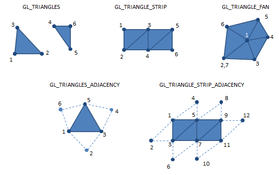
You may need to adjust the size of m_pts in rectangle.h to hold the appropriate number of vertices when specifying your rectangle geometry. When copying the data to the VBO, ensure that the triangles are oriented counter-clockwise according to the drawing order. Note for a GL_TRIANGLE_STRIP, the first triangle uses vertices p1, p2, p3, and the second triangle uses vertices p3, p2, and p4, flipping the order of p2 and p3 automatically when drawing the second triangle.
Try creating and drawing a rectangle in initializeGL() to test your implementation. You can create a rectangle using code similar to the following:
QVector2D p1(-0.5, -0.5);
QVector2D p2( 0,  1);
Rectangle* rect = new Rectangle(m_gpuIhfo, p1, p2);
rect->setColor(QVector3D(0,0,1));
m_shapes.append(rect);
Once you have a rectangle drawing correctly, implement your copy constructor and try creating a second rectangle using the copy constructor to verify it works correctly.
6.1. Implementing contains for Rectangle
Use the leftOf function to determine if a point is inside the rectangle. Think carefully about how your points are ordered in m_pts and create your vectors accordingly.
7. Drawing a Circle
Next, implement the Circle class in circle.cpp. You will need to create both the .h and
.cpp files and add them to CMakeLists.txt. The circle is defined by a center point and a radius. You will need to approximate the circle using a polygon with many sides. A good number of sides to use is 30-40, which should look fairly smooth. You can define the vertices of the polygon using trigonometric functions (sine and cosine) to compute the x and y coordinates of each vertex around the circle.
Circle::Circle(GPUHelper *const help, const vec2& center, float radius)Use a for loop and add a number of points along the perimeter of the circle in counter clockwise order.
\$x = \cos(\theta)\$
\$y = \sin(\theta)\$
\$0 \leq \theta \leq 2 \pi\$
Consult the OpenGL primitives image above to see how to draw a circle as a sequence of triangles. You may need to think carefully about how to order the vertices in the local points buffer and VBO.
Create a circle in initializeGL() to test your implementation. Then implement and test your copy constructor.
7.1. Implementing contains for Circle
To determine if a point is inside the circle, you can compute the distance from the point to the center of the circle and compare it to the radius. If the distance is less than or equal to the radius, the point is inside the circle. No need to use leftOf for this one.
8. Implementing a Line
Finally, implement the Line class in line.cpp. You will need to create both the .h and .cpp files and add them to CMakeLists.txt. A line is defined by two endpoints. You can draw the line using the GL_LINES drawing mode.
Line::Line(GPUHelper *const help, const vec2& p1, const vec2& p2, float tolerance)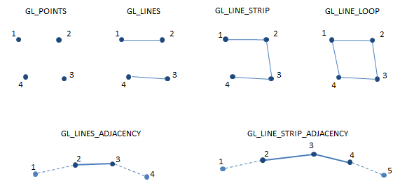
There are no real orientation tests here. A line is just two points.
8.1. Implementing contains for Line
It is difficult to click exactly on a line, so we will define a line to contain a point if the point is within a certain tolerance distance from the line segment. This tolerance is set in the constructor. You can compute the distance from a point to a line segment using vector projection. If the projected point falls outside the segment, use the distance to the nearest endpoint instead. If the computed distance is less than or equal to the tolerance, return true, otherwise return false.
While crossProduct is only defined for 3D vectors, dotProduct is defined for both 2D and 3D vectors. You can use QVector2D::dotProduct(v1, v2) to compute the dot product of two 2D vectors.
9. Testing shapes
Create a scene in initializeGL() with a few triangles, rectangles, circles, and lines. You can use the copy constructors to create multiple copies of each shape. Move and color the shapes to create a scene of your choosing. It doesn’t have to be too elaborate. We will build better live editing tools for your shapes next week.
By default, the application enables the culling of triangles oriented clockwise. This is done in initializeGL() with the call to glEnable(GL_CULL_FACE);. If you want to see both sides of your shapes, you can disable back face culling by commenting out this line, but the shapes should be oriented CCW so that they are drawn correctly when culling is enabled.
You can add a few tests of the contains method in initializeGL() to verify that it works correctly, but we will do more testing of this next week.
10. Summary of Requirements
Your project will be graded on the following components:
-
Implementations of Triangle, Rectangle, Line, and Circle shapes
-
All derived shape classes have a working draw method
-
All derived shape classes have a working copy constructor
-
OpenGL primitives for Triangle, Rectangle, and Circle oriented counter-clockwise
-
Create a scene containing at least two objects of each type and containing at least three colors
-
A reasonable attempt at implementing the contains method for each shape. You will have a chance to improve this next week, but don’t ignore it completely.
-
Answers to the concept questions in the README.adoc file
-
All changes added, committed, and pushed to team repo on Swarthmore GHE
You will not be graded on the lab survey questions in the Readme.adoc file
Submit
Once you have edited the files, you should publish your changes using the following steps:
$ git add <files you changed>The git add step adds modified files to be part of the next commit to the github server.
$ git commit -m "completed lab2"The git commit step makes a record of the recently added changes. The -m "completed lab1" part is a descriptive message describing what are the primary changes in this commit. Making a commit allows you to review or undo changes easily in the future, if needed.
$ git pushThe git push command sends your committed changes to the github server. If you do not run git push before the submission deadline, I will not see your changes, even if you have finished coding your solution in your local directory.
If you make changes to files after your push and want to share these changes, repeat the add, commit, push loop again to update the github server.
If you want to commit changes to files that have already been committed to git once, you can combine the add and commit steps using
$ git commit -am "bug fix/updates"The -a flag will automatically add files that have been previously committed. It will not add new files. When in doubt, use git status, and please do not use git add * ./
To recap, the git commit cycle is git add, git commit, git push. Don’t forget to git push when you have completed an assignment.
Optional Extensions
These extensions are entirely optional and should not be attempted until the required components are complete.
-
Add a new shape type like an ellipse or quad (not necessarily right angled)
-
Add a complex shape type that is specified by the corners of a bounding box, e.g., a simple tree could be a derived Drawable type containing a triangular or circular canopy with a modifiable color, and rectangular, fixed color trunk.
-
Add support for shape outlines and setting the outline color and width. Note,
glLineWidthmay be crippled. Let me know if you experience weirdness implementing this. You should callglEnable(GL_LINE_SMOOTH);ininitializeGL()to enable the line width operation.
Errata
GLSL syntax highlighting
If you are using vscode and your GLSL files do not have syntax highlighting, you can add it by installing the Shader languages support for VS Code extension (or GLSL linter) from the vscode extensions marketplace.